This document describes the standard testing procedure for testing vape's compatibility with FRIENDS v1 monitor
Standard operating procedure of vape testing
INTRODUCTION AND PURPOSE:
This Standard Operating Procedure (SOP) following procedure describes testing that determines if puffing on a certain vape model is detectable by the FRIENDS device.
MINIMUM EQUIPMENT REQUIRED:
|
1 |
Charger for vape |
|
2 |
Charger for FRIENDS Device |
|
3 |
Putty for wrapping vape’s mouthpiece |
|
4 |
3D printed mouthpiece adapter |
| 5 |
A Vacuum pump/line for drawing puffs |
|
6 |
Markers- green, yellow, red |
|
7 |
Laptop for documentation |
|
8 |
Protective gloves |
PROCEDURES:
1. Charge the vape: Ensure the vape is completely charged before conducting tests. It will prevent the risk of generating weak pulses to be detected by the RF sensor in the FRIENDS device. Use the vape charge indicator to ensure a complete charge.
2. Charge the FRIENDS device: Use a micro-USb cable and a USB charger to charge the FRIENDS device. A blue LED light will remain on while the device is being charged. The blue light will go off once the charge is complete.
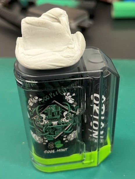
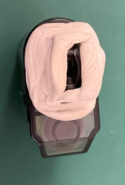
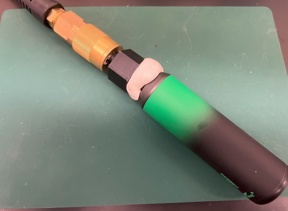
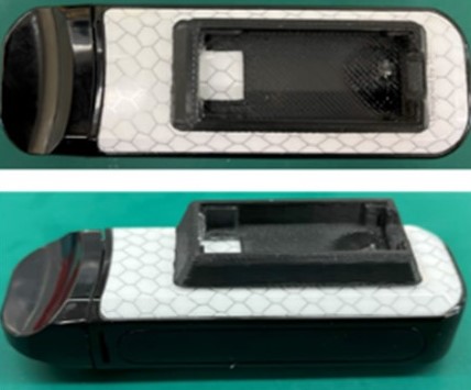
3. Wrap the vape's mouthpiece with putty: To ensure reliable puffing, the vape's mouthpiece has to be connected to a vacuum line. The connection has to be airtight and have no leaks. The recommended connection is to use reusable mounting putty (such as Loctite Fun-Tak Low Strength Synthetic Rubber Mounting Putty), wrapping the putty around the mouthpiece as shown below.
|
|
|
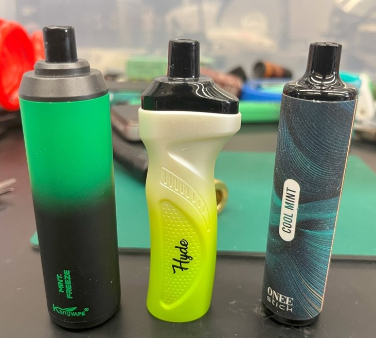
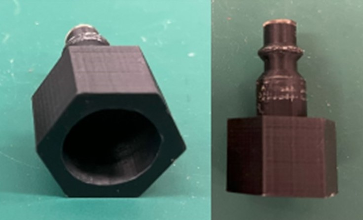
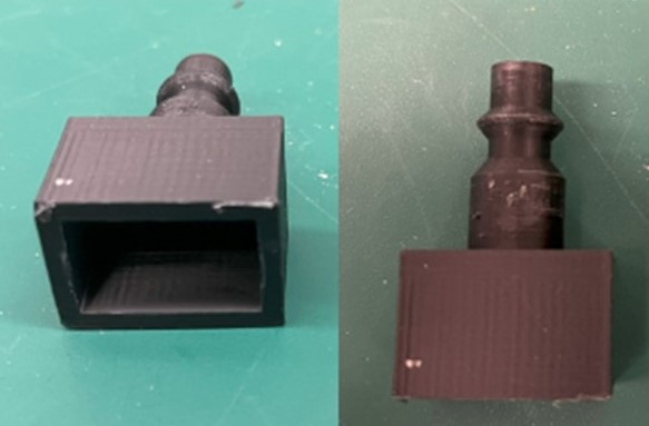
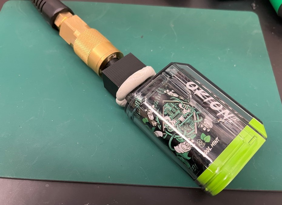
4. Attach the vape to the vacuum line: The vacuum is used to simulate puffing. The user must be able to control puffs either through a mechanical (e.g. foot pedal) or electromechanical valve. Mouthpiece adapters accommodate for an airtight connection for a variety of mouthpiece shapes. Links to 3D adapter models are provided below. The adapters can be attached to a standard air hose connector. Examples of vapes connected to a vacuum line are shown below.
|
Mouthpiece type |
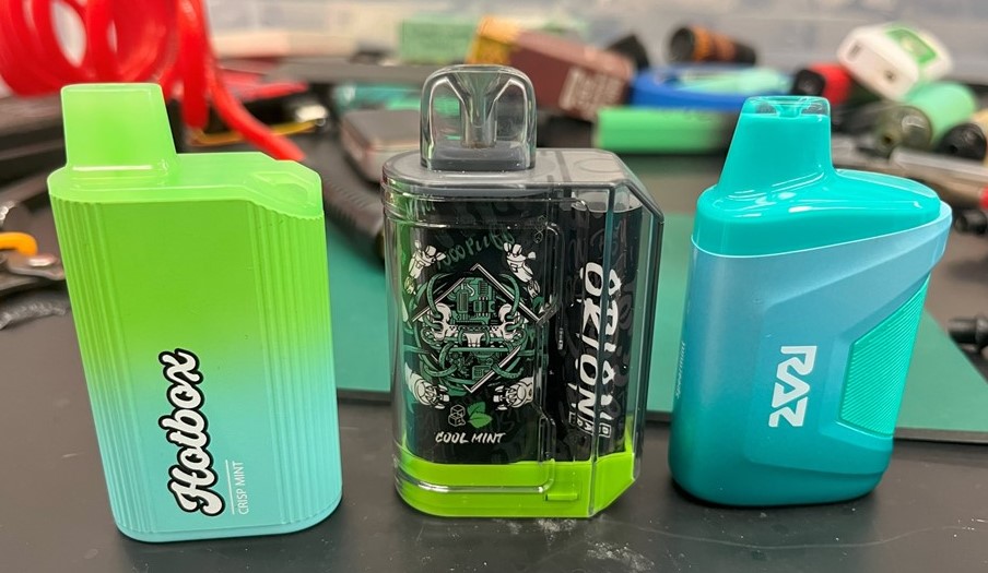
Vape Sample |
Mouthpiece Adapter |
Vape connected to the vacuum line |
|
Cylindrical-shaped mouthpiece |
|
Link to the 3D model |
|
|
Box-shaped mouthpiece |
|
Link to the 3D model |
|
5. Identify the vape type and connectivity zones: Not every vape produces pulses, and even if it does, these pulses may not occur uniformly across the entire surface. Besides, some vapes may display puff detection through the green LED (in FRIENDS device) across the complete surface, but there are cases where it's only noticeable in specific areas. The FRIENDS device categorizes vapes into three types based on their ability of detecting puff.
- Detectable (stable green) in response to the puff
- Partially detectable (short green blink in response to puff on/off)
- Non-detectable, no response to puffs
To identify the vape types with FRIENDS device, some common steps need to be followed.
Testing steps to categorize vape types:
|
Step no. |
Steps |
|
|
1 |
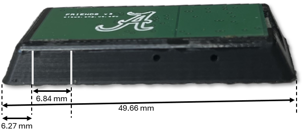
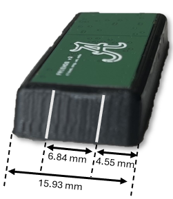
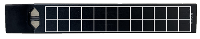
Mark the two sides of the enclosure with silver lines to identify RF sensors’ location maintaining 6.84 mm distance in between. |
|
|
2 |
Mark the entire body of the vape with rectangular grids, each measuring 6.84 mm in width and length. |
|
|
3 |
Begin on one side of the vape and initiate from the rectangular grid located at the top left corner. |
|
|
4 |
Place the RF sensor (identified with silver markings) at that location on the surface of the vape |
|
|
5 |
Initiate puff by the vacuum for 2 seconds |
|
|
6 |
Observe the Green LED of the device |
For stable green, mark the location with a green marker |
|
For short green blink, mark with yellow |
||
|
Mark the location as red for no LED illumination |
||
|
7 |
Perform steps 5 and 6 an additional two times and document the records |
|
|
8 |
Move to the next location |
|
|
9 |
Repeat the tasks from step 4 - 8 until all the surface of the vape is covered |
|
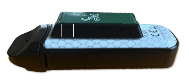
Marking the enclosures to identify the RF sensor's location:
 |
 |
 |
An illustrative example of documenting records:
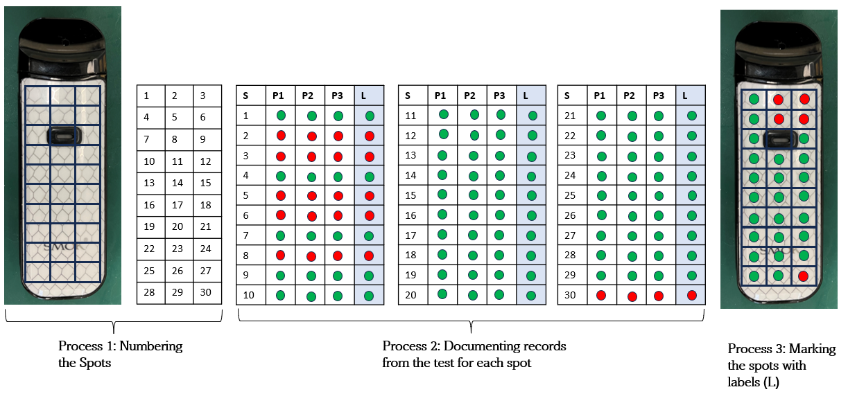
Process 1: Create rectangular grids on each side of the vape's surface and assign numbers to these rectangles in your own document (e.g., doc, pptx), following the instructions illustrated in step 1 of the figure. Please note that the quantity of grids may differ depending on the type of vape, yet each grid should match the dimensions of the RF sensor, measuring 6.84 mm by 6.84 mm. There are no hard and fast rules for determining the number of grids, but it's important for test takers to attempt to cover the entire surface of the vape with grids of the specified dimensions. For instance, a JUUL might have fewer grids compared to a Smok: Nord 2. An illustration of this can be seen with the JUUL vape.
 |
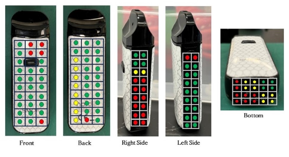
Process 2: You will identify the locations’ behavior by performing a repetitive test on every location of the vape, with three puffs at each location. Then, mark the results (green, yellow, red) in the documentation based on the tests done in steps 5, 6, and 7 for every set of three puffs at each spot. Final Labeling (L) procedure:
- Green label: When all three puffing events show green markings.
- Yellow label: If there's at least one yellow marking and no red markings.
- Red label: If there's at least one red marking among the three.
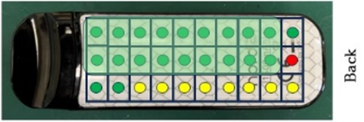
Process 3: From the labels (L) created in process 2, mark the spots of the vape with the labels (L) in your documentation.
Identify vape types:
|
Vape Category |
Description |
|
Detectable |
Vapes with green marks present on at least some area of the device’s body |
|
Partially detectable |
Vapes lacking green markings, with only yellow and red marks visible on the body |
|
Non-detectable |
Vapes with only red marks on their body |
During the test, false positive puffs may occur due to the RF sensor's sensitivity to electromagnetic signals nearby. Hence, testers must be cautious when monitoring the green LED to ensure that its illumination is triggered solely by puffs generated through the vacuum line.
6. Make Documentation: It is required to identify the most appropriate positions for all the vapes that produce electrical pulses to attach the FRIENDS device and make a documentation of it. Test takers should choose the mounting location for the device based on the green marked connectivity zones. It should prioritize user-friendly grabbing, ensuring no interference with button pressing (if any), minimal discomfort, and alignment of the RF sensor within the green area. The recommended mounting location is indicated by green shaded area as shown in the table provided below
|
Vape Brand |
Sensitivity zones |
Type of Detection |
Recommended Mounting Location |
|
Smok : Nord 2 |
|
Detectable |
|
Note: All procedures must be performed while wearing protective gloves. And at the end, clean the work area from any leftover debris.
For downloading the checklist of essential steps for vape testing: Click here